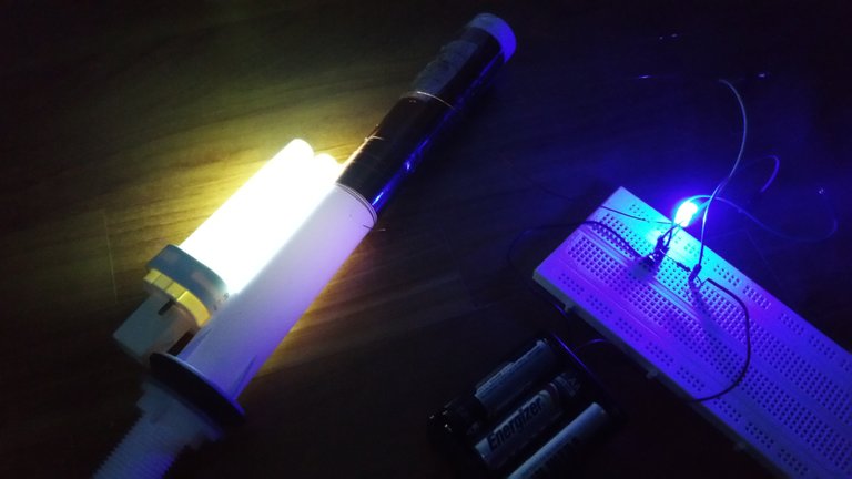
It can light a fluorescent lamp wirelessly using high voltage!
A Slayer Exciter is an inverting circuit that produces high voltage AC from low voltage DC. I made one myself some time ago and posted it elsewhere, and now I will share it on steem:
I came across the Slayer Exciter circuit, found it to be quite simple to build and decided to try it out. It is basically a transformer that uses a transistor to alternate the DC input to produce AC on the primary coil. The large number of turns on the secondary results in a high voltage.
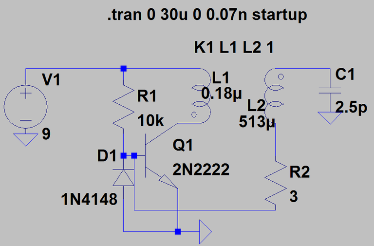
After modelling the circuit with LT Spice, I managed to figure out how the circuit works. The following is a bit difficult to understand so you may want to skip it.
A small current flows through R1 into the transistor's base. This allows a current to flow through L1. Due to the inductance of L1, the current slowly increases through L1. This induces a current through L2 to charge the C1 to a negative voltage. C1 cannot discharge into the ground as D1 is blocking, thus it goes through the base of the transistor, allowing L1 current to continue flowing. Since L2 and C1 forms an LC circuit, at some point, the C1 voltage is too negative that the current stops flowing.Now, the base current suddenly drops, causing the L1 current to drop drastically until the current through L1 hits 0. Next, current flows through D1 and L2 to increase the voltage of the negatively charged C1. However, no current flow through L1 as there is no base current. The current through D1 and L2 increases and until C1 voltage hits 0, then starts to decrease from there, thus charging C1 to a positive voltage. This is once again due to the current-change-resisting property of the inductor. Now C1 discharges its positive voltage through the transistor base, allowing current low through L1. The cycle starts again.
The theoretical output assuming perfect transformer coupling is as shown below. The voltage variation reaches around 3kV, with a period of around 0.3us.

My slayer exciter uses around 300 turns of magnet wire around a PVC pipe and around 3.5 turns of thicker enameled wire as the primary. A 2N2222 is used for the transistor. However,the 2N2222 in its typical TO-92 package, it gets very hot quickly. If the slayer exciter runs for more than 30 seconds, the transistor will likely burn out. For the diode, I tried a 1N4148 but it did not work. Instead, a blue LED works, and doubles as an indicator. The resistor value can be anywhere from 10k-100k Ohms. The power source is 6x1.5V AA batteries. I tried using a 9V battery at first but the internal resistance was too high. A high primary current is needed for the slayer exciter and thus it is crucial to keep the internal resistance as low as possible.
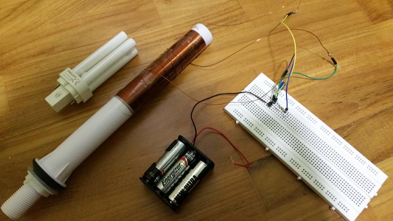
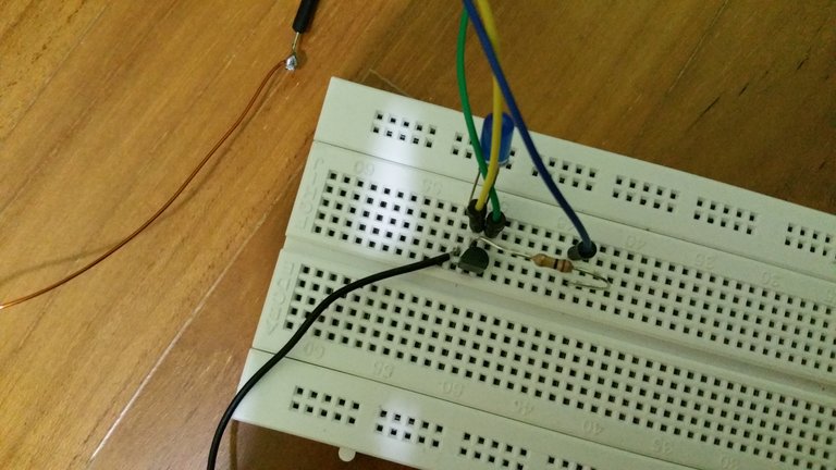
In the picture below, you can see it in operation. The fluorescent lamp is not connected to the circuit and lights up wirelessly. This is due to the strong electric field produced by the high voltage.
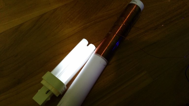
With the lights completely off, we can see the the brightness of the lamp more clearly.

For future extensions, I intend to switch out the 2N2222 to a 2N3055 in a TO-3 package so that it can handle more power. A top load can also be made to have a higher capacitance for the primary coil.
Im an electrical engineering student and this is very essential in my field.
Tanx alot@frostfractal
Wil b expecting more from u
Kudos
Thanks! Great to see someone from electrical engineering!
UeArai @frostfractal
What is the nature of the magnetic wire? Can Copper wire suffice? I'm trying to figure out an alternative way to improvise this, and yet get the result done.
Nice piece. Upvoted, Followed, and Resteemed
I used enameled copper wire. It just has to be very thin so that you can wrap many turns.
Does it cause radio interference?
Didn't test that, but I believe it does!
Nice, thankyou for sharing @frostfractal
Congratulations @frostfractal! You have completed some achievement on Steemit and have been rewarded with new badge(s) :
<p dir="auto"><a href="http://steemitboard.com/@frostfractal" target="_blank" rel="noreferrer noopener" title="This link will take you away from hive.blog" class="external_link"><img src="https://images.hive.blog/768x0/https://steemitimages.com/70x80/http://steemitboard.com/notifications/voted.png" srcset="https://images.hive.blog/768x0/https://steemitimages.com/70x80/http://steemitboard.com/notifications/voted.png 1x, https://images.hive.blog/1536x0/https://steemitimages.com/70x80/http://steemitboard.com/notifications/voted.png 2x" /> Award for the number of upvotes received <p dir="auto">Click on any badge to view your own Board of Honor on SteemitBoard.<br /> For more information about SteemitBoard, click <a href="https://steemit.com/@steemitboard" target="_blank" rel="noreferrer noopener" title="This link will take you away from hive.blog" class="external_link">here <p dir="auto">If you no longer want to receive notifications, reply to this comment with the word <code>STOP <blockquote> <p dir="auto">By upvoting this notification, you can help all Steemit users. Learn how <a href="https://steemit.com/steemitboard/@steemitboard/http-i-cubeupload-com-7ciqeo-png" target="_blank" rel="noreferrer noopener" title="This link will take you away from hive.blog" class="external_link">here!Your post was mentioned in the hit parade in the following categories:Congratulations @frostfractal!
This is technological advancement we appreciate in the present world.
Hello. I am physical and athlete. Very goog post electricity.
Follow me