Circuits and Symbols

In this article, we’ll look at electronic circuits, that is, interconnections of electronic components. As you recall, in the last article, we looked at a particular electronic component, the resistor. We’ll look at resistors in more detail in this lecture, but we’ll also learn how to represent many other kinds of electronic devices in circuits and how to read circuit diagrams. In addition, we’ll begin to see how to interconnect electrical systems. Key topics we’ll cover are:
- Components and their symbols
- The ideal battery
- Voltage-current characteristics
- Series components: resistors
- A simple circuit: the voltage divider
- Real batteries
- Parallel components: resistors.
Components and Their Symbols

A simple electrical circuit might consist of a 1.5-V battery connected with 1000-Ω resistor. This circuit has a source of electrical energy, a battery, and a load, something to which that energy is supplied. That load might be a loudspeaker, a motor, or as here, simply a resistor.

The symbols that represent circuits constitute a language to learn.
The Ideal Battery

A battery is a simple example of a voltage source. It converts chemical energy into electrical energy, and it produces, in principle—if it’s ideal— exactly the same voltage across its terminals, regardless of how much current it supplies.
Voltage-Current Characteristics

To describe the voltage-current (V-I) characteristics of an ideal 6-V battery, we can draw a graph with voltage (V) on the horizontal axis and current (A) on the vertical axis. The resulting V-I characteristic curve is a straight vertical line—6 V, regardless of current. We can draw a similar graph for a 1-Ω resistor. The resulting curve for the resistor is a straight diagonal line with a slope of 1 A for every volt.

Series Components: Resistors

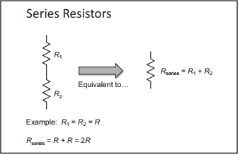
Two electric components are in series if the current flowing through one of them has nowhere to go but into the next one. Because the current that’s flowing through one device goes into the other, the same current flows through both components.

Imagine we have two resistors, R1 and R2. Because current through R1 can flow only through R2, the two are in series. Resistors in series simply add; thus, the series resistance is the sum of the two resistances.
A Simple Circuit: The Voltage Divider

A voltage divider is basically two series resistors, R1 and R2 , across some source of voltage, V. This device divides the voltage in proportion to the resistances.

One special case of a voltage divider is when R1 and R2 are equal. In that case, the output voltage, or the voltage across R2 , is ½ V. If R2 is 0, we get no voltage across it; it’s a perfect wire. If R2 is much greater than R1 , then V2 is almost equal to the battery voltage; R1 becomes almost a perfect wire if R2 is much greater than R1.
Real Batteries

To model a real battery, imagine an ideal battery in series with a resistor, representing the battery’s internal resistance. Real batteries or any real sources of voltage have internal resistance, which must be taken into account to use them correctly. The loads put across them can’t be too low so we don’t drop a voltage across that internal resistance, which would make the voltage across the battery terminals much lower than the battery’s rated voltage.
Parallel Components: Resistors

Two components are in parallel if the two ends of each component are connected, and therefore, they have exactly the same voltage across either of them.

Parallel combination is sometimes called a current divider because current coming into the combination splits between R1 and R2 , with more current going through the lower resistance.
Questions to Consider
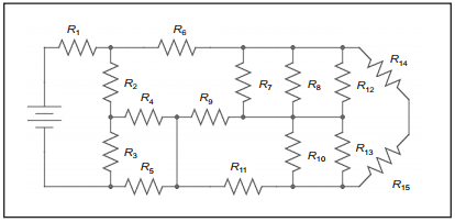
Identify pairs of series and parallel components in the circuit below.

A 6-V battery has an internal resistance of 0.25Ω. If you connect a 5-Ω resistor across the battery, what will be the voltage across the battery’s terminals?

