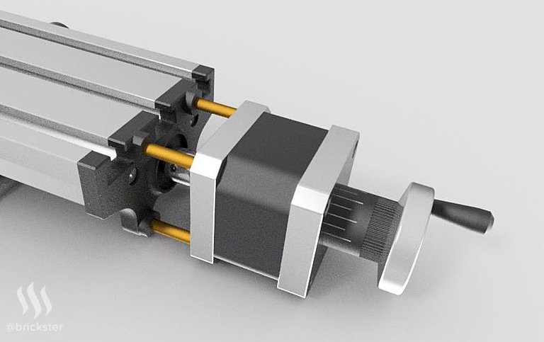
Today I want to show you my design for the stepper motor mount that for the X-axis. I wanted to create them so that it can still be used manually. Therefore I needed to create a new shaft for the stepper motor which is shorter on the front side to connect to the threaded rod and longer on the backside to fit the original adjusting wheel. Moreover I had to keep in mind to minimize the distance between the platform and the motor to reduce the momentum along the Y-axis.

I need to manufacture following parts:
1x sideplate with mounts to insert the distance pipes
4x distance pipes
1x cluch to connect the engine shaft with the threaded rod
1x threaded rod (adjusted length, not shown above)
1x stepper motor shaft
The sideplate will be 3D printed with PLA and the shaft and cluch will turned/ machined.

If you are interested in the first part where I show more renderings of the mill, please check out the link:
https://steemit.com/design/@brickster/cnc-conversion-1-cad-model-renderings
Ich möchte euch gerne meine Konstruktion für die Halterung des Schrittmotors der X-Achse zeigen. Mir war dabei wichtig, dass die manuelle Bedienung erhalten bleibt. Außerdem ist zu beachten, den Abstand von Motor zu Tisch möglichst gering zu halten um ein möglichst geringes Moment um die Y-Achse zu erzeugen, was anderenfalls zu Ungenauigkeiten im Betrieb führen kann.
Ich muss folgende Teile dafür selbst herstellen:
1x Seitenplatte mit Aufnahmen für die Distanzrohre
4x Distanzrohre
1x Kupplung um die Welle des Motors mit der Gewindestange zu verbinden
1x Gewindestange (nur angepasste Länge der Originale)
1x Welle für den Schrittmotor
Das Seitenteil wird voraussichtlich 3D gedruckt aus PLA, die Welle und Kupplung gedreht aus Stahl/Alu.
Falls du am ersten Teil interessiert bist, in dem ich paar Renderings von der Maschine selbst zeige,bitte hier klicken:
https://steemit.com/design/@brickster/cnc-conversion-1-cad-model-renderings
Ich versteh zwar nur Bahnhof, war aber bestimmt viel Arbeit :D
Vielen Dank! Ja das war es allerdings. :)