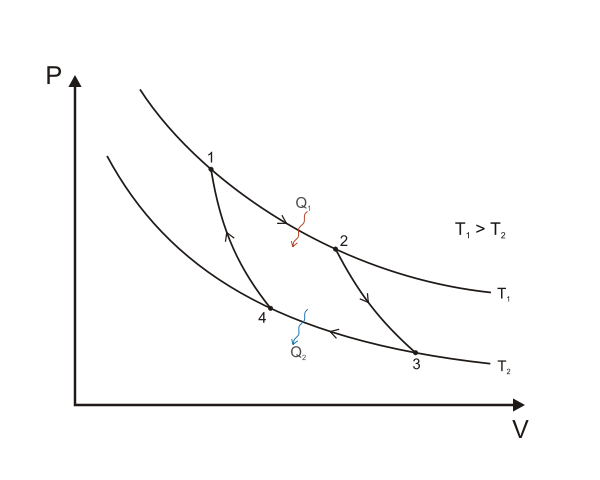
Did you know that two isotherms and two adiabatics (the names given to the changes)can be put together to produce a closed cycle? Actually, this is called a Carnot cycle. In a closed cycle, we finish at the same pressure, volume, and temperature at which we started. The Carnot cycle is not the only cycle we can produce on a pV diagram, since we can also have changes at constant volume and constant pressure or other changes, as well as isothermal and adiabatic changes. If we follow the cycle in the clockwise direction shown, we see that the gas does not work on its surroundings equal to the area enclosed by the cycle. This is similar to finding the work done by taking a series of strips of area pΔV but here the strips go from a lower pressure to a higher pressure such that each strip has an area of (Phigher – Plower) ΔV.

A Carnot cycle illustrated on a PV diagram to illustrate the work done. Keta, CC BY-SA 3.0
THE CARNOT ENGINE
Thermodynamics limits the amount of work that can be extracted between the hot source and the cold sink. An engine operating using the Carnot cycle consisting of two adiabatics and two isothermals is the most efficient engine possible. It has an important feature: it can be operated in reverse. It is called a Carnot engine and is the standard by which other engines are compared. A Carnot engine cannot actually exist – it is just an imaginary ideal engine in which there are no energy losses, such as through friction and conduction.
The Carnot cycle is a special case of a reversible cycle. All ideal engines using a reversible cycle and working between the same two temperatures have the same efficiency, but the Carnot engine uses the simplest reversible cycle. Real engines do not use reversible cycles and so have a much lower efficiency.
The temperatures of the hot source and cold sink are crucial to the amount of work that can be extracted. We might expect this as we know from everyday experience that when engineers are designing an internal combustion engine or the operation of the turbines of a power station they try to achieve high temperatures on the input side.
It turns out that we can define the source temperature Th and the sink temperature Tc in terms of the ratio of the thermal energies Qh And Qc transferred:
Th/Tc = Qh/Qc
Note that the temperatures Th and Tc are measured on the Kelvin scale – this is very important. Although I won’t go into details here, this relationship between the temperatures and energy inputs and outputs can be used for defining the thermodynamic scale of temperature, and the scale agrees completely with the scale defined by using a constant-volume gas thermometer and the triple point.

HEAT TRANSFER IN THE ENGINE
If Qh = ‘heat’ input (from hot source), W= work done and Qc = ‘heat’ output (thermal losses to cold sink), then:
Qh = W + Qc
The amount of work done in a cycle equals the amount of energy actually used. However, it is not possible to do this work without a thermal loss of energy. That is, there must be a thermal sink.
THE DIESEL ENGINE
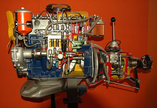
Diesel engine is similar to the internal combustion engine but there is no fuel in the cylinder at the beginning of the compression. Air is taken into the cylinder during an intake stroke 1,2. When this point is reached, the inlet valve is closed. The air in the cylinder is next compressed adiabatically along 1,2 such that there is a large compression ratio. This means that the volume at 3 is very small compared with that at 2. This produces a high temperature at 3. Fuel is sprayed into the cylinder at C and ignites because of this high temperature. The input of fuel can be carefully controlled such that there is an expansion 3,4 at constant pressure (that is there is an isobaric expansion). Injection of fuel now stops and the cylinder continues to move such that there is an adiabatic expansion to E. The cylinder has at this stage moved fully, a valve opens, and the pressure immediately drops. This corresponds to returning to point B on the pV diagram. This is followed by an exhaust stroke of the cylinder back along BA to drive out the gases in the cylinder such that the cycle can begin again.
The higher efficiency of the Diesel engine compared with the internal combustion engine arises from the large compression ratio which can be typically as high as 20. However, even a Diesel engine cannot match the efficiency of the ideal, but hypothetical, Carnot engine.
EFFICIENCY
The efficiency of an engine is defined by:
(The work done by the engine ÷ The energy supplied by the engine) × 100 %
Which can be expressed as:
W/Qh × 100 %
But the work done is the difference between the energy supplied and the energy given to the sink (conservation of energy), that is, Qh - Qc. So the efficiency of the engine is given by:
(Qh - Qc) ÷ Qh × 100 % = (1 - Qc/ Qh) × 100 %
For an ideal reversible cycle such as a Carnot cycle this equals
= (1 - Tc/ Th) × 100 %
EXAMPLE
A power station uses superheated steam (at high pressure) at approximately 500°C. The cold sink corresponds to the temperature at which steam condenses at atmospheric pressure, that is, 100 °C. What is the maximum theoretical efficiency for the power station?
ANSWER: Using the equation for the efficiency of an ideal cycle:
Efficiency = (1 - Tc/ Th) × 100 %
= (1 – 373/773) × 100 %
= (1 – 0.48) × 100 %
= 52 %
Real engines
From the thermodynamics we can see that it is nowhere near possible to get 100% efficiency from an engine. But so far we have taken no account of the mechanical inefficiency of the engine itself. Modern technology has been gradually improving efficiencies but no engine can be produced with zero friction.
The nominal input power is given by:
Rate of fuel flow × calorific value of the fuel
On the other hand, the power we would obtain thermodynamically is given by:
area contained within one pV loop × number of cycles per second × number of cylinders making the loops
Obviously an amount of work pV is done every cycle if there are no losses and most engines have a number of cylinders (four or six are common in car petrol engines).
The actual output power is often measured by the Torque T that can be produced at angular frequency ω multiplied by this frequency ω, i.e. Tω, and is called brake power. (Tω is equivalent to a force multiplied by a distance divided by a time, which is power. The power brake consisting of a belt wrapped around a flywheel under tension T was invented by Lord Kelvin.)
The lost power or friction power is then:
(thermodynamic power calculated) – (brake power)
Diesel engine model. I, Luc Viatour, CC BY-SA 3.0
REFRIGERATORS AND HEAT PUMPS
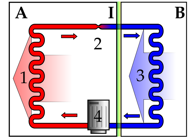
I mentioned that a Carnot engine is reversible. In real life, we operate cycles reversibly to remove energy from a cold source and get rid of this energy at a higher temperature. Refrigerators and freezers do this. Here the cooling cycle involves the evaporation of a low boiling point liquid in the refrigerator. The energy for this evaporation comes from the internal energy of the contents of the refrigerator, but we need a source of work.
The vapour is condensed using a compressor. This compressor, of course, does work using energy from the electrical mains. As the vapour is compressed and condensed, it gets hotter and loses (dissipates) its energy thermally through a long metal pipe at the back of the refrigerator. So, overall, internal energy extracted from the food is dissipated by the element which becomes warm at the rear of the cabinet. Hence, a refrigerator will warm the room it is in.
The energy transfer in a refrigerator is shown in the same way as that of the heat engine. The efficiency, or more appropriately the coefficient of performance, as values can be greater than 100 per cent, is defined by:
Energy extracted from the cold source ÷ work done by the compressor
= Qc/W × 100 %
= Qc/(Qh – Qc) × 100 %
= Tc/(Th – Tc) × 100 %
(Again the temperature relationship refers to an engine operating reversibly, such as one with a Carnot cycle.)
A heat pump, operates in a similar way to a refrigerator by extracting energy thermally from a cold source such as a river and delivering it into a body such as a house at a higher temperature. Here we are interested in the amount of internal energy added to the house rather than the amount extracted from the river, so we define the percentage coefficient of performance by:
energy added to the hotter body ÷ work done by the pump
= Qh/W × 100 %
= Qh/(Qh – Qc) × 100 %
= Th/(Th – Tc) × 100 %
(again assuming an ideal reversible cycle)
On the basis of this equation, heat pumps look very attractive. A small amount of work can be used to transfer a large amount of thermal energy. In practice, real heat pumps turn out to have a much lower efficiency than the efficiency of an ideal heat pump based on the Carnot cycle. Heat pumps also have high capital cost, partly because they are not made in large numbers.
In addition, although energy can be continually extracted thermally from neighbouring river (assuming the river does not freeze up), extracting internal energy from other sources such as neighbouring ground can lead permanent frozen conditions.

HEAT PUMPS AND ENTROPY
I have already shown that entropy is a measure of disorder. When energy is transferred thermally to a body, this increases the disorder. We can measure the entropy change best if the temperature remains constant. For example, suppose we add energy thermally to a solid at its melting point. The resulting liquid is more disordered than the solid and the molecules move around randomly with a range of speeds. The change of entropy ΔS can be shown to be related to the change of thermal energy ΔQ by:
ΔS = ΔQ/T
Where T is temperature measured on the Kelvin scale.
We can also assume constant temperature when we extract from, or put energy into, a large reservoir. When the temperature is not constant, working out the entropy change becomes more difficult (and usually involves calculus). We can consider the change of entropy that occurs when a heat engine operates. Here we can assume that the hot source and the cold sink remain at constant temperature. See an example below.
EXAMPLE
A heat engine operates between 373 K and 300 K and has an efficiency of 18 per cent. What is the change of entropy when work of 1000 J is done by the engine?
ANSWER: First we find the transfer of energy from the hot source.
1000 J of work is done with 18 per cent efficiency. Therefore, (100/18 × 1000) J must be transferred from the hot source. That is: Q1 = 5560 J
Loss of entropy of the hot source = Q1/T = 5560/373 J K-1 = 14.9 J K-1
Gain of energy by the heat sink = Q2 = Q1 – W = (5560 – 1000) J = 4560 J
Gain of entropy of the heat sink = Q2/T = 4560/273 J K-1 = 16.7 J K-1
Net change in entropy = 1.8 J K-1
As we have come to expect, there is a net increase in entropy.
POSTSCRIPT THE THIRD LAW
There is a third law of thermodynamics. It states that the entropy of a system approaches a constant value (zero in a simple system) as the temperature approaches absolute zero. To achieve zero temperature requires an infinite number of steps – we have to extract a bit of energy, and a bit more, and a bit more and so on. A practical statement of the law is: It is impossible to achieve absolute zero temperature for a system by a finite number of steps.
At the start of this series of post, we saw that a temperature less than 1 billionth of a kelvin has been reached. This statement of the third law tells us that we shall never get to 0 K.
SUMMARY
In these series of posts of mine on Thermodynamics, I provided a statement of the zeroth law and indicated its application to temperature measurement. I provided a statement of the first law and applied the equation ΔU = ΔQ + ΔW. I carried out calculations for isothermal (constant temperature) and isobaric (constant pressure) changes of an ideal gas. I used the relationship between Cv and Cp for an ideal gas in calculations.
I also explained the relationship pVY = constant in calculations for an adiabatic change of volume of an ideal gas. I provided a statement of the second law and explained its importance. I explained the concept of entropy, S = k In W, and change of entropy, ΔS = ΔQ/T, and calculated ΔS values for simple applications.
Finally, I made clear the principles underlying heat engines, refrigerators and heat pumps and carried out simple calculations, including those for efficiencies (or coefficients of performance).
REFERENCES
http://hyperphysics.phy-astr.gsu.edu/hbase/thermo/carnot.html
https://en.wikipedia.org/wiki/Carnot_cycle
http://hyperphysics.phy-astr.gsu.edu/hbase/thermo/carnot.html
https://en.wikipedia.org/wiki/Carnot_heat_engine
https://www.engr.colostate.edu/~allan/heat_trans/page1/page1.html
http://web.mit.edu/2.61/www/Lecture%20notes/Lec.%2018%20Heat%20transf.pdf
http://eng.pdn.ac.lk/old/mechanical/menu/class/downloads/notes/02-Engine%20heat%20transfer.pdf
https://www.howacarworks.com/basics/how-a-diesel-engine-works
https://dieselnet.com/tech/diesel_history.php
https://www.explainthatstuff.com/diesel-engines.html
https://www.britannica.com/technology/diesel-engine
https://forum.kerbalspaceprogram.com/index.php?/topic/171335-realenginespack-201-close-010418/
https://en.wikipedia.org/wiki/Carnot_heat_engine
https://en.wikipedia.org/wiki/Heat_pump_and_refrigeration_cycle
https://web.mit.edu/16.unified/www/FALL/thermodynamics/notes/node25.html

This post has been voted on by the SteemSTEM curation team
and voting trail. It is elligible for support from @curie and @minnowbooster.
If you appreciate the work we are doing, then consider supporting our witness @stem.witness. Additional witness support to the curie witness would be appreciated as well.
For additional information please join us on the SteemSTEM discord and to get to know the rest of the community!
Thanks for having used the steemstem.io app and included @steemstem in the list of beneficiaries of this post. This granted you a stronger support from SteemSTEM.